
Today's automotive designers have been under relentless pressure to develop ever more fuel efficient and compact automobile engines that are also low-maintenance. To achieve these benefits considerable compromises have been made. Some of these compromises, their advantages and their disadvantages are listed in Table I.
Table I: Modern Piston Design Compromises |
||
|
Modern Piston Design Compromise |
Design Advantage |
Disadvantage |
|
Engines run hotter. |
More complete combustion, thus lower emissions and higher fuel efficiency. |
Problems due to hotter parts, thus a greater need to reduce wear and friction. |
|
Piston clearances are much lower (typically .001˝ to .0005˝ or less). |
More wear and noise in mis-aligned pistons. |
|
|
The top compression rings are placed closer to the top of the piston |
The top compression ring sees higher temperatures (up to 600 oF) thus can increase ring groove distortion, microwelding and pound-out failure. |
|
|
Compression rings are made thinner. |
Less friction thus higher fuel efficiency. Before this change, rings accounted for up to 40% engine internal friction losses. |
Thinner rings are less able to handle bore distortion or mis-alignment and there is lower heat transfer out of the piston. |
|
Engines designed to go more miles before overhaul. |
Less maintenance. |
Parts must last longer. |
|
The wrist pins are moved higher up on the piston, especially in some aftermarket pistons to account for resurfacing on the block and heads. |
Allows the use of longer connecting rods, which improve torque and reduces stresses on the bearings and rings. |
Lower thermal conduction on the top of the piston head. |
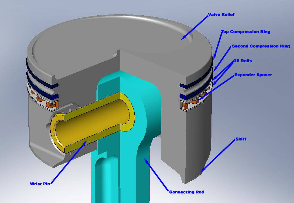
Figure 1: A sectioned view of a model piston assembly.
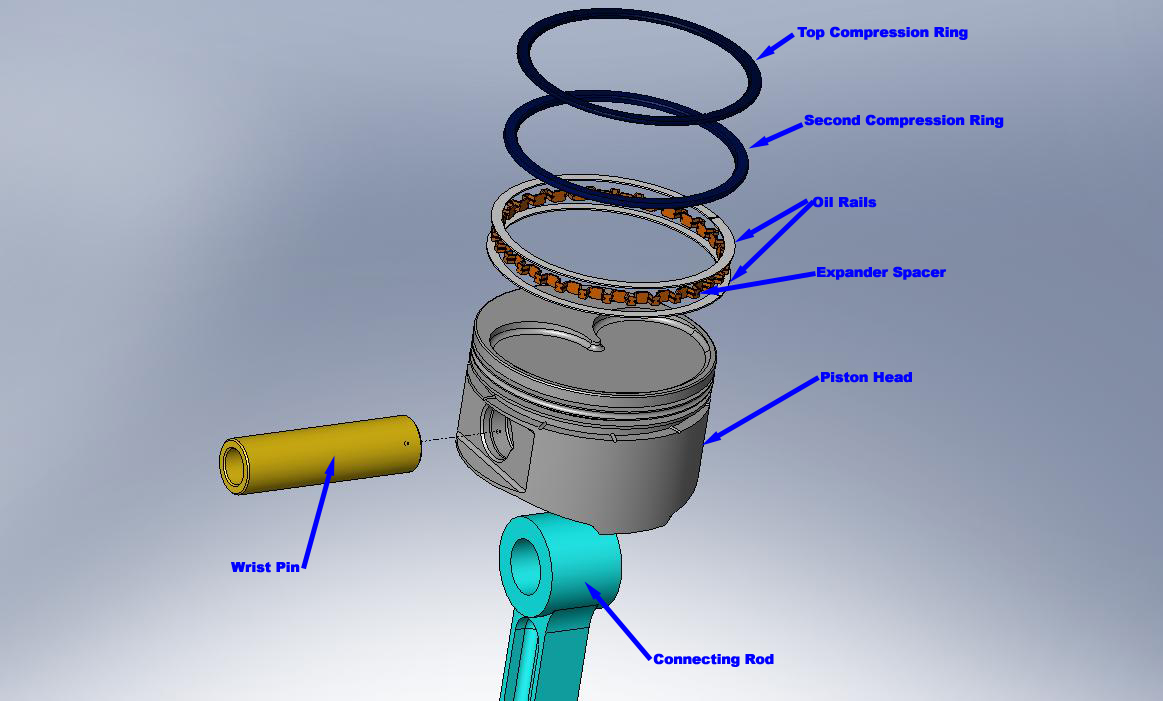
Figure 2: An exploded view of a model piston assembly.
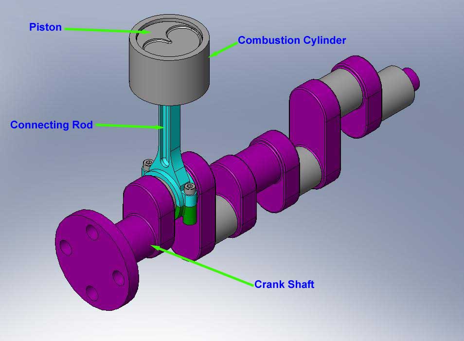
Figure 3: A crank shaft turning a connecting rod which moves a piston within a cylinder.
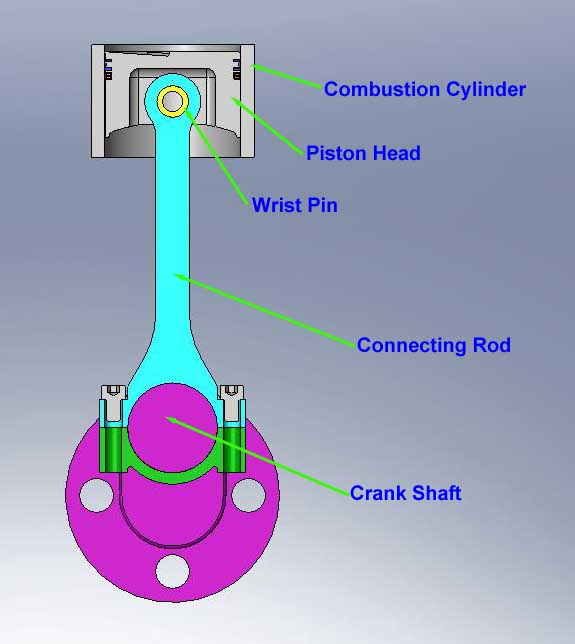
Figure 4: A sectioned view of a the complete assembly.
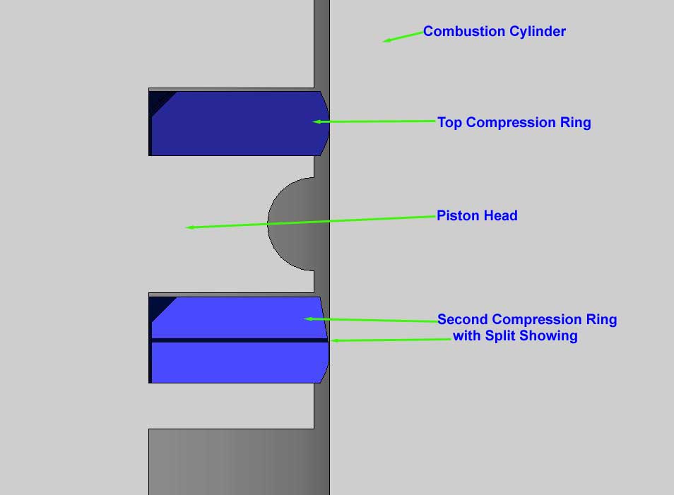
Figure 5: A close-up & sectioned view showing the compression ring contact with the combustion cylinder. Notice that the compression rings are not held rigidly within the piston head. There are gaps at the tops of each compression ring and there is also a gap between the inner diameter of each compression ring and the piston head.
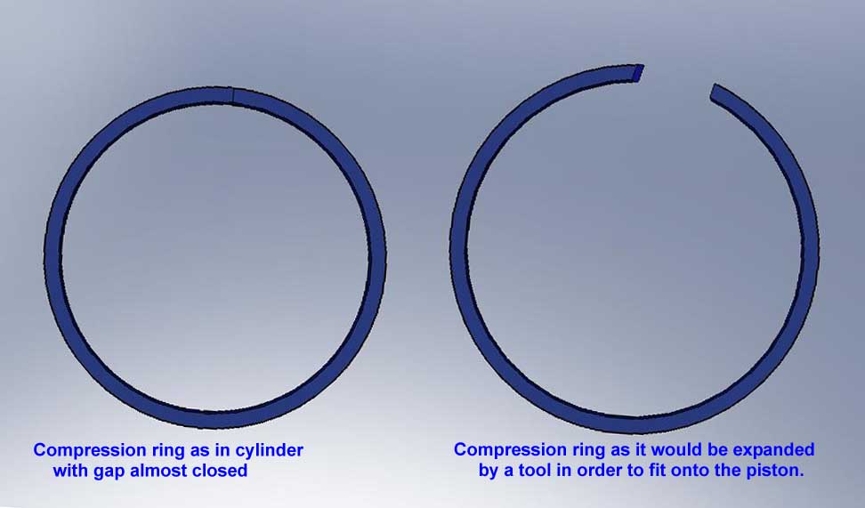
Figure 6: The cast iron or steel compression rings are split in order to insert them onto monolithic piston head castings. This split is shown in both Figures 5 and 6.
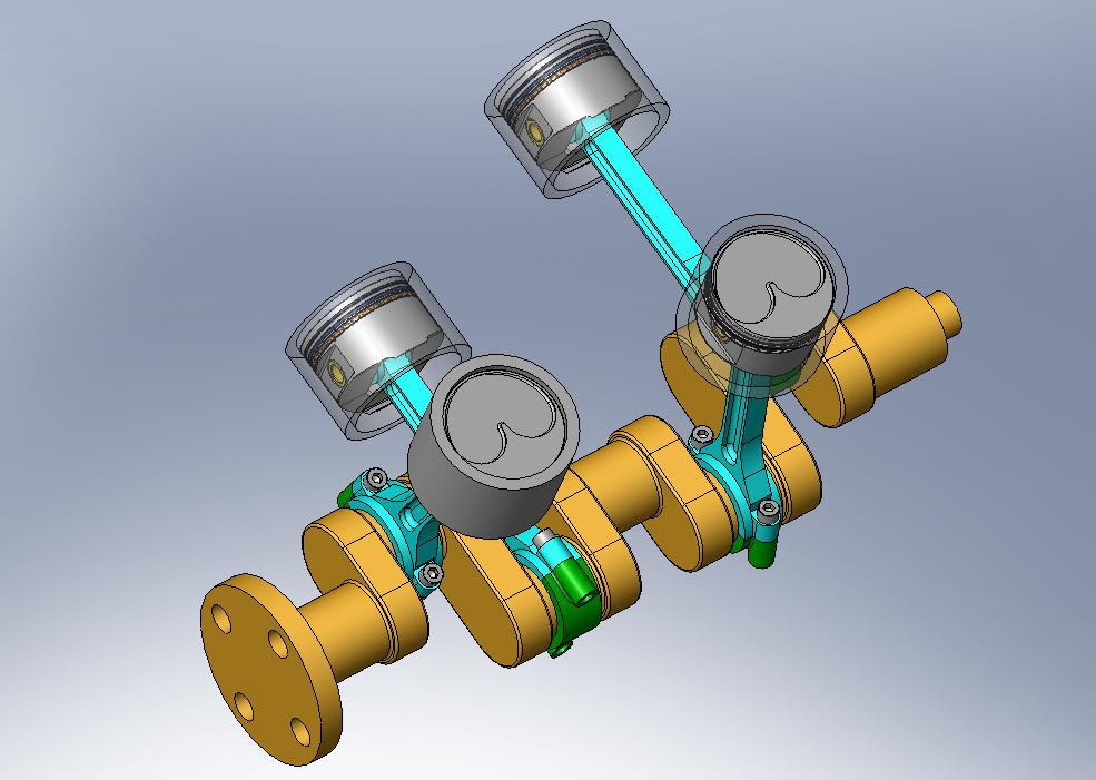
Figure 7: Click the image above to view animations of the engine components.